Are your solids the same as my solids?
29 Jun 2015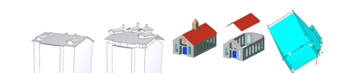
While the definitions found in the OGC/ISO Simple Features specifications for 2D primitives are well-accepted and used in practice by virtually everyone in the GIS community, I have noticed that the ones for 3D primitives (especially for the volumetric primitive, called a solid or a polyhedron) are in almost all cases ignored by software vendors, by practitioners, and even by academics1. Many GIS vendors now offer 3D capabilities, but unfortunately they take great liberties in defining what “3D GIS” means—and no a perspective view on a 2.5D terrain does not qualify as 3D GIS in my opinion.
It seems to me that each vendor is currently implementing its own version of what it thinks a solid should be. Or, perhaps more accurately, the definition of a solid is driven by what can be technically achieved by the vendor (and since holes and cavities are complex to model in a computer, they are almost in all cases ignored). To make things worse, the different definitions of solids used are rarely documented. Exchanging and converting datasets from one format/platform to another is thus at this moment highly problematic, and in my opinion hinders severely the use and the development of 3D functions.
To help practitioners dealing with 3D objects, I explain below what a 3D solid is according to the international standard, and I try to give as many insights as possible to explain what these mean.
To be fair, even mathematicians don’t agree…
I must admit that representing a solid is far more complex than representing a 2D polygon, and that different disciplines use rather different definitions. This is best illustrated by Grünbaum (2003)23, who states that even in the field of mathematics opinions differ as to what constitutes the term “polyhedron”. Some use it only for a regular polyhedron, or only for a convex one, and some consider non-planar faces as part of the definition. The authoritative textbook on computational geometry4 characterises the term as “difficult to define”, and give a simple definition that is probably the most common one: a polyhedron is a 3D solid bounded by planar faces. The bounding faces are thus planar surfaces embedded in the 3D Euclidean space, and the bounding surfaces form a two-dimensional manifold (or 2-manifold for short). A 2-manifold is a topological space that is topologically equivalent to a 2D space—an obvious example is the surface of the Earth, for which near to every point the surrounding area is topologically equivalent to a plane.
What is an ISO19107 solid?
The international standard ISO19107 definition of a solid is broader than that of a 2-manifold, and it permit us to represent all the real-world features. It is basically a generalisation to 3D of a polygon, which can have interior boundaries/rings:
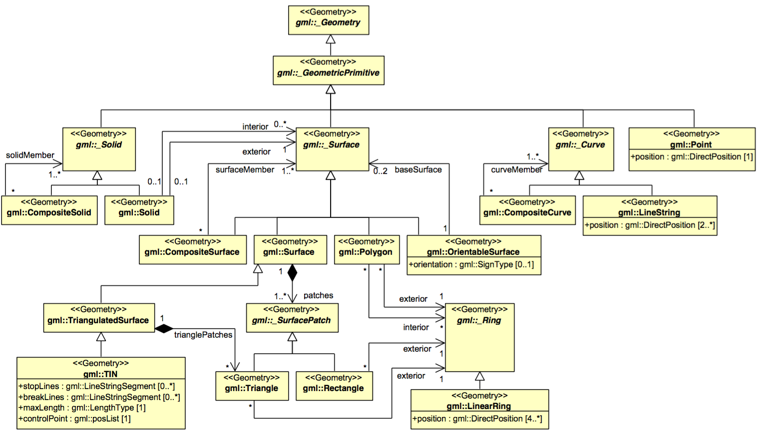
The ISO19107 geometric primitives are:
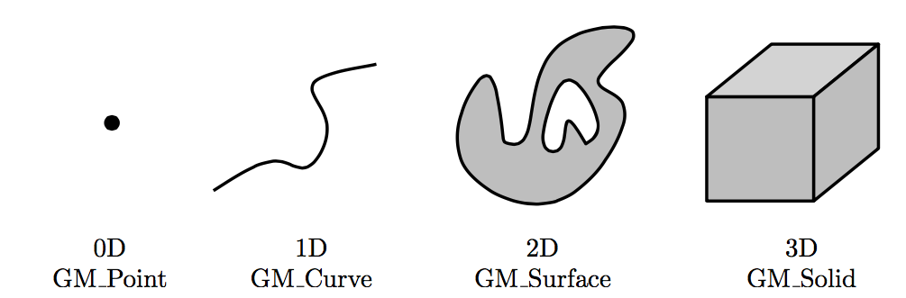
A primitive is built with lower-dimensional primitives, eg in the figure above the GM_Surface is composed of 2 (closed) GM_Curves, which are composed on several GM_Points.
Observe that primitives do not need to be linear or planar, ie curves defined by mathematical functions are allowed.
In our context, the following three definitions from ISO19107 are relevant:
A
GM_Solidis the basis for 3-dimensional geometry. The extent of a solid is defined by the boundary surfaces. The boundaries ofGM_Solidsshall be represented asGM_SolidBoundary. […] TheGM_OrientablesSurfacesthat bound a solid shall be oriented outward.
A
GM_Shellis used to represent a single connected component of aGM_SolidBoundary. It consists of a number of references toGM_OrientableSurfacesconnected in a topological cycle (an object whose boundary is empty). […] LikeGM_Rings,GM_Shellsare simple.
A
GM_Objectis simple if it has no interior point of self-intersection or self-tangency. In mathematical formalisms, this means that every point in the interior of the object must have a metric neighbourhood whose intersection with the object is isomorphic to an n-sphere, where n is the dimension of thisGM_Object.
The bounding surfaces of a shell thus form a closed and orientable 2-manifold. Closed means that there should not be ‘holes’ in the surface (in other words, it should be watertight).
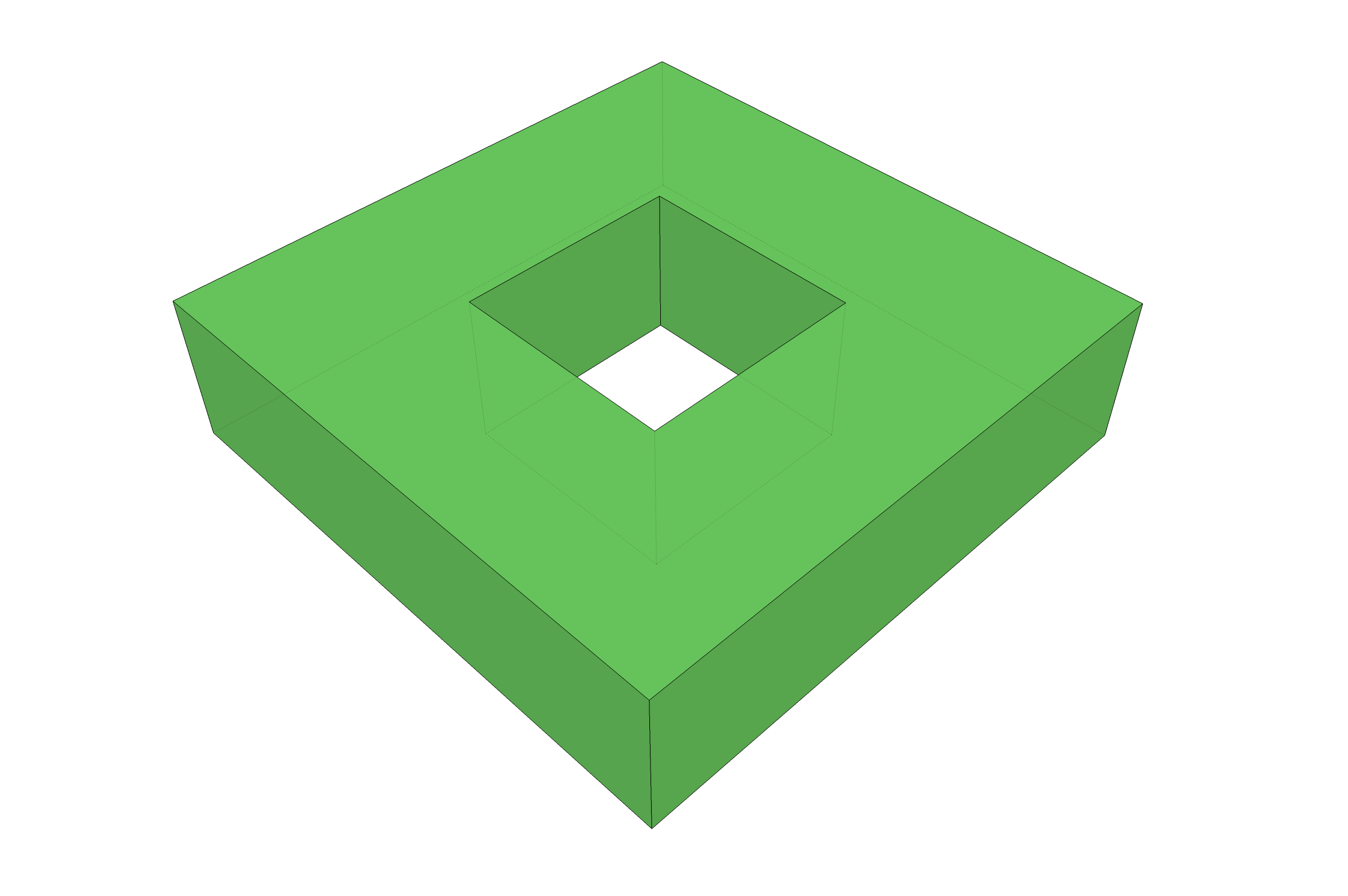
A solid that respects that definition is as follows:
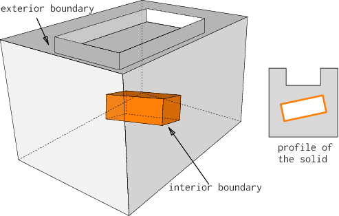
First observe that the solid is composed of two shells (both forming its boundaries), one being the exterior and one being the interior shell. This is conceptually the same as a 2D polygon that has an inner ring. The exterior shell has eleven surfaces, and the interior one six. An interior shell creates a cavity in the solid—cavities are also referred to as ‘voids’, or holes, in a solid. A solid does not need to have an interior shell, and can contain an infinity of them.
Observe that a cavity is not the same as a hole in a torus (a donut) such as that in the following figure: it can be represented with one exterior shell having a genus of 1 (there are no interior shell).
Assertions to verify the validity of a solid
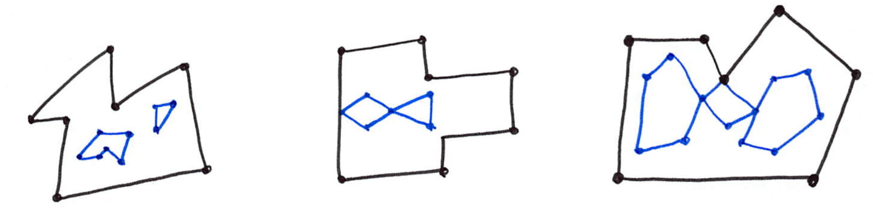
According to the ISO19107 abstract specifications, the different boundaries of a solid are allowed to interact with each other, but only under certain circumstances. Since there is no implementation specifications (yet?) for 3D primitives, we have to generalise the following assertions for the validity of a 2D polygon (which you can find on pages 27-28 of the Simple Features document):
- Polygons are topologically closed;
- The boundary of a Polygon consists of a set of LinearRings that make up its exterior and interior boundaries;
- No two Rings in the boundary cross and the Rings in the boundary of a Polygon may intersect at a Point but only as a tangent, eg \(\forall P \in Polygon, \forall c1, c2 \in P.Boundary(), c1 \neq c2,\) \(\forall p, q \in Point, p, q \in c1, p \neq q, [p \in c2 \Rightarrow q \notin c2];\)
- A Polygon may not have cut lines, spikes or punctures, eg \(\forall P \in Polygon, P = P.Interior.Closure;\)
- The interior of every Polygon is a connected point set;
- The exterior of a Polygon with 1 or more holes is not connected. Each hole defines a connected component of the exterior.
Observe that all of them, except the 3rd one, generalise directly to 3D since a point-set topology nomenclature is used. The only modifications needed are that, in 3D, polygons become solids, rings become shells, and holes become cavities.
To further explain what the assertions are in 3D, the figure below shows 12 solids, some of them valid, some not; all the statements below refer to these solids.
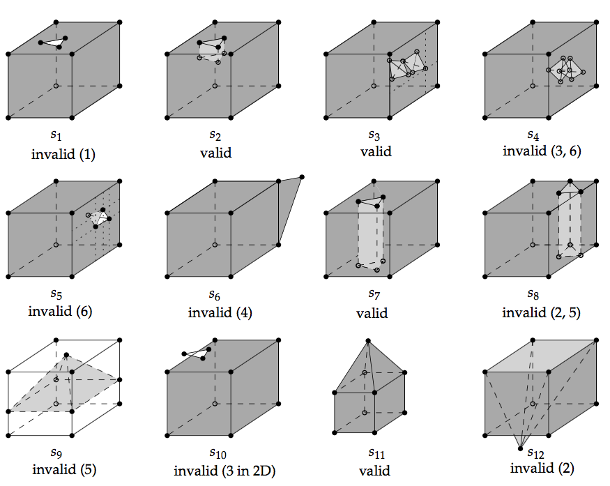
The first assertion of the OGC means that a solid must be closed, or ‘watertight’ (even if it contains interior shells). The solid s1 is thus not valid but s2 is since the hole in the top surface is `filled’ with other surfaces.
The second assertion implies that each shell must be simple (ie a 2-manifold).
The third assertion means that the boundaries of the shells can intersect each others, but the intersection between the shells can only contain primitives of dimensionality 0 (vertices) and 1 (edges). If a surface or a volume is contained, then the solid is not valid. The solid s3 is an example of a valid solid: it has two interior shells whose boundaries intersect at one point (at the apexes of the tetrahedra), and the apex of one of the tetrahedra is coplanar with the 4 points forming one surface of the exterior shell. If the interior of the two interior shells intersects (as in s4) the solid is not valid; this is also related to the sixth assertion stating that each cavity must define one connected component: if the interior of two cavities are intersecting they define the same connected component. Notice also that s5 is not valid since one surface of its cavity intersects with one surface of the exterior shell (they “share a surface”); s5 should be represented with one single exterior shell (having a ‘dent’), and no interior shell.
The fourth assertion states that a shell is a 2-manifold and that no dangling pieces can exist (such as that of s6); it is equivalent to the regularisation of a point-set in 3D.
The fifth assertion states that the interior of a solid must form a connected point-set (in 3D). Consider the solid s7, it is valid since its interior is connected and it fulfils the other assertions; notice that it is a 2-manifold but that unlike other solids in the figure (except s8) its genus is 1. If we move the location of the triangular prism so that it touches the boundary of the exterior shell (as in s8), then the solid becomes invalid since its interior is not connected anymore, and also since its exterior shell is not simple anymore (2 edges have 4 incident planar faces, which is not 2-manifold). It is also possible that the interior shell of a solid separates the solid into two parts: the interior shell of s9 (exterior shell is not coloured for clarity) is a pyramid having four of its edges intersecting with the exterior shell, but no two surfaces are shared, thus these interactions are allowed. However, the presence of the pyramid separates the interior of the solid into two unconnected volumes (violating assertion 5); for both s8 and s9, the only possible valid representation is with two different solids.
Notice also that for a solid to be valid, all its lower-dimensionality primitives must be valid. That is, each surface of the shells has to be valid according to the Simple Features assertions. An example of an invalid surface would be one having a hole (an inner ring) overlapping the exterior ring (see s10).
Furthermore, it should also be noticed that for a solid to be valid both its topology and its geometry should be valid. A solid such as s11 is valid, but if the location of only one of its vertices is modified (for instance if the apex of the pyramid of s11 is moved downwards to form s12) then it becomes invalid. Both s11 and s12 can be represented with a graph having exactly the same topology (which is valid for both), but if we consider the geometry then the latter solid is not valid since its exterior shell is not simple.
OK, theory is nice, but what do people do in practice?
While in theory GML allows one to implement non-planar primitives, in practice, for most practical uses, only linear/planar primitives are used.
CityGML actually uses only a subset of the ISO19107 primitives: (1) GM_Curves can only be linear (thus only LineStrings and LinearRings are used); (2) GM_Surfaces can only be planar (thus `Polygons are used).
Since the polygons are embedded in 3D, they have to be planar: all their points (used for both the exterior and interior rings) have to lie on a plane. Surprisingly, the concept of tolerance is not mentioned in the standards ISO and OGC, thus it is difficult to answer clearly whether a polygon is planar or not.
Lastly, the orientation of the polygons must be considered. In 2D, the only requirement for a polygon is that its exterior ring must have the opposite orientation of that of its interior ring(s) (eg clockwise versus counterclockwise). In 3D, if one polygon is used to construct a shell, its exterior ring must be oriented in such as way that, when viewed from the outside of the shell, the points are ordered counterclockwise. See for instance this solid and the orientation of three of its polygons (different colours).
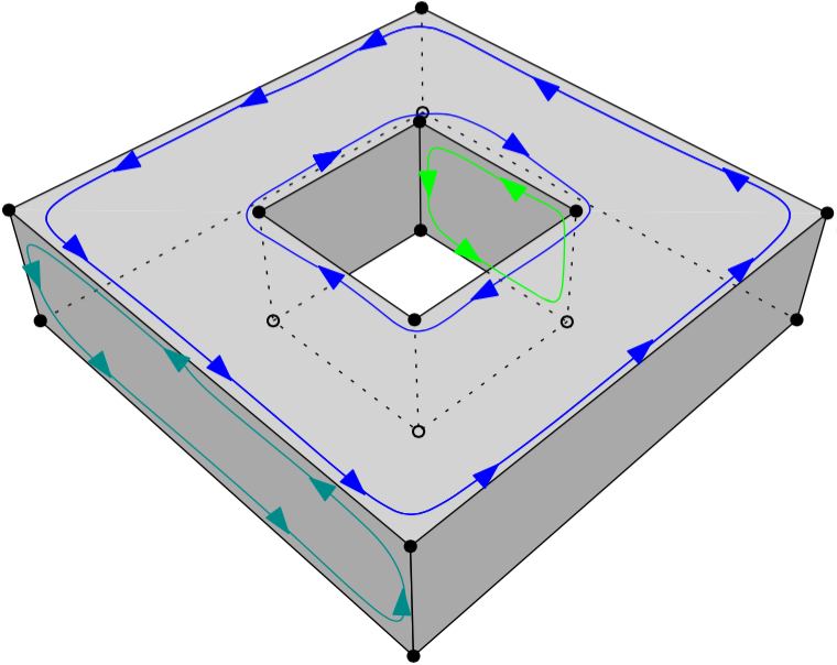
In other words, the normal of the surface must point outwards if a right-hand system is used, ie when the ordering of points follows the direction of rotation of the curled fingers of the right hand, then the thumb points towards the outside. If the polygon has interior rings, then these have to be ordered clockwise.
val3dity: a validator for GML primitives
If you have solids stored in GML, you can verify whether they follow the ISO19107 definitions by using the validator (called ‘val3dity’) I have developed. The code is freely available on GitHub, and I offer a web application where you can upload your GML files and get a report detailing the errors.
Futher reading
Most of the details of the implementation and the methodology used are available in this scientific article:
Ledoux, Hugo (2013). On the validation of solids represented with the international standards for geographic information. Computer-Aided Civil and Infrastructure Engineering, 28(9):693-706. [PDF] [DOI]
-
we have the—deserved!?—reputation of over-complicating simple things, so I’m puzzled as to why even academics in GIS tend to reduce solids to much simpler objects. ↩
-
B. Grünbaum. Are your polyhedra the same as my polyhedra? In B. Aronov, S. Basu, J. Pach, and M. Sharir, editors, Discrete and Computational Geometry: The Goodman-Pollack Festschrift, pages 461– 488. Springer, 2003. ↩
-
yes, the title of this blog post is heavily inspired by that of Grünbaum (2003). ↩
-
M. de Berg, M. van Kreveld, M. Overmars, and O. Schwarzkopf. Computational geometry: Algorithms and applications. Springer-Verlag, Berlin, second edition, 2000. ↩
